
Serving East Arthedain, Rivendell and The Shire since 1967
Buckland remodelled
CBUS and MERG
CBUS is a highly flexible, adaptable and modular model railway layout control system designed, developed, tested and used by members of MERG (Model Electronic Railway Group).
Set up in 1967 MERG is an international group, based in the UK, which promotes the use of electronics and computers in all aspects of railway modelling. Members are model railway enthusiasts who are interested in applying electronics to the operation of their model railways and the Group enables members to exchange ideas and information, and provides kits covering a number of interests including DC operations, DCC, Radio Frequency Identification, computer control and CBUS.
A CBUS installation consists of two or more modules which communicate with each other via a bi-directional local area bus network (in practice, just two wires). A number of standard modules have been designed that carry out a range of tasks, including:
| CBUS Module | Use | Capacity |
| CAN_ACE3 | Monitors buttons and switches on control panels | 128 inputs |
| CAN_LED64 | Illuminates LEDs on control panels or within the scenery | Drives up to 64 separate LEDs |
| CAN_ACE8C | General input module for sensors, switches other input devices | 8 inputs, or 16 with modification |
| CAN_TOTI | Reports the status of DCC track occupancy detectors | 8 inputs |
| CAN_ACC4 | Operates solenoid point motors | 4 point motors |
| CAN_SERVO8C | operates servos | 8 servos |
| CAN_SIG | Automatic control of colour light signals | Up to 4 signals |
| CAN_ACC8 | operates relays and other high current devices | 8 outputs (500mA each) |
| CAN_USB | Connects to a PC for module programming or to use the computer as a virtual control panel, for automatic train control or layout automation | |
Modules are taught how to respond to messages transmitted across the network. For example, a train moving onto a section of track monitored by an occupancy detector (CAN_TOTI) would trigger a message to be broadcast which, via other modules, could illuminate lights on a control panel (CAN_LED64), change one or more points (CAN_ACC4), change the state of signals (CAN_SIG) and close the gates of a level crossing (CAN_SERVO8C).
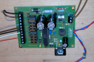
A CAN_ACE4 CBUS module, for operating point motors.
The two brown wires supply power, the red and blue pair are the
network data cables and the wires on the left connect to the point motors
For basic, manual operation of points two types of module are required: an input module, such as a CAN_ACE3, to encode button presses on a control panel, and a CAN_ACC4 which independently controls up to four solenoid point motors. The CAN_ACC4, which operates like a Capacitor Discharge Unit, can interpret up to thirty two different messages and operate any or all of the attached point motors. Since one message can be acted upon by many CBUS modules, simply pressing one button can set an entire route by changing multiple points.
There are over 70 installed modules on the layout, with the possibility of more in the future. The following is a map of the installed network and its power supplies:

CBUS module map showing layout of installed network