
Serving East Arthedain, Rivendell and The Shire since 1967
Buckland remodelled
DCC equipped locomotives are more sensitive to wheel electrical pickup performance than analogue DC systems. Smooth running, particularly at slow speeds and for shunting locomotives with few wheels, can be significantly improved by the addition of 'Stay Alive' (aka 'Keep Alive') power modules that can provide power to the DCC decoder when supply from the track is temporarily interrupted. Some decoders have this capability built in whilst others have connections or wires that can be connected to Stay Alive modules.
A typical Stay Alive is built around one or more capacitors that are charged when the decoder is receiving track power and discharge when that supply is lost. Although they may only work for up to a few seconds, this is enough to prevent the decoder shutting down and allows the motor to keep running, propelling the locomotive until the wheels can pick up track power again.
Many decoders can be modified to use Stay Alive and examples are shown here.
Basic Stay Alive Circuit

This circuit, suggested by the decoder manufacturer Zimo, is used on a number of the locomotives.
The blue wire refers to that on the wiring harness of the decoder and is the +V supply used by lights and accessories.
The 68 Ohm resistor limits the inrush current that charges the capacitors to prevent an overload and cut-out of the DCC track booster.
The 1N4001 diode bypasses the resistor when the capacitors discharge on loss of track power.
The 3K3 Ohm slowly discharges the capacitors when the loco is removed from the track to prevent unexpected decoder behaviour as the voltage falls.
The Zener diode limits the maximum voltage across the capacitors to 15V to protect them from overvoltage damage.
I have not used the choke in my modules as I haven't observed any problems when programming Stay Alive equipped decoders. If necessary I can always disconnect the Stay Alive.
The 0V connection to the decoder is potentially the most complex part of the installation. Some decoders have a dedicated 0V wire or solder pad, whilst on the rest you must identify a place on the decoder to solder an additional wire.
The six capacitors used are AVX SCCQ12B105SRB rated at 1 Farad and a maximum of 2.7V. When connected in series the total capacitance is 1 Farad divided by 6 (the number of capacitors), or 0.166 Farads (166,000uF). The maximum voltage that can be applied across the capacitors in series is 2.7V multiplied by 6, or 16.2V. The Zener diode will protect the capacitors should the voltage rise above its rated 15V.
These capacitors have an Equivalent Series Resistance of 200 mOhms. This is the internal resistance of the capacitor, and the lower the value the better as ESR represents an internal voltage drop when high current is drawn from the capacitors. For six in series, the total resistance is 6 x 200mOhms = 1.2 Ohms, which gives an acceptable voltage drop of about 0.25V if the decoder is drawing 200mA from the Stay Alive.
More information about the theory and calculations can be found at Mark Gurries excellent page about Stay Alive devices.
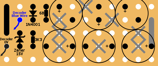
Veroboard circuit layout, viewed from component side. Grey 'X' denotes a cut in the copper track on the reverse.

Veroboard, viewed from reverse, showing location of copper track cuts.


Completed Stay Alive Module
Installation with a Zimo MX600 decoder
Installation with a Bachmann 36-553 decoder
Two wires (+V and 0V) are required to connect the Stay Alive to the decoder. The decoder's blue +V wire (used for accessories and lights) can be used but I have chosen to add a new +V wire direct to the board to keep the wiring neat. There is no 0V wire in the decoder's wiring harness so one must be added to the board.
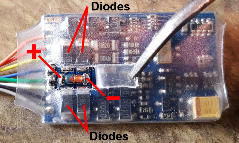
Connection points for +V and 0V wires to Stay Alive module. There are four diodes (two above and two below the cut in the
plastic cover) that make a bridge rectifier. The component between them connects between the +V (left) and 0V (right).

Wires soldered to the +V and 0V points. Instead of adding the red +V wire, you could just use the blue wire in the decoder
harness instead as it is effectively connected to the same point in the circuit.
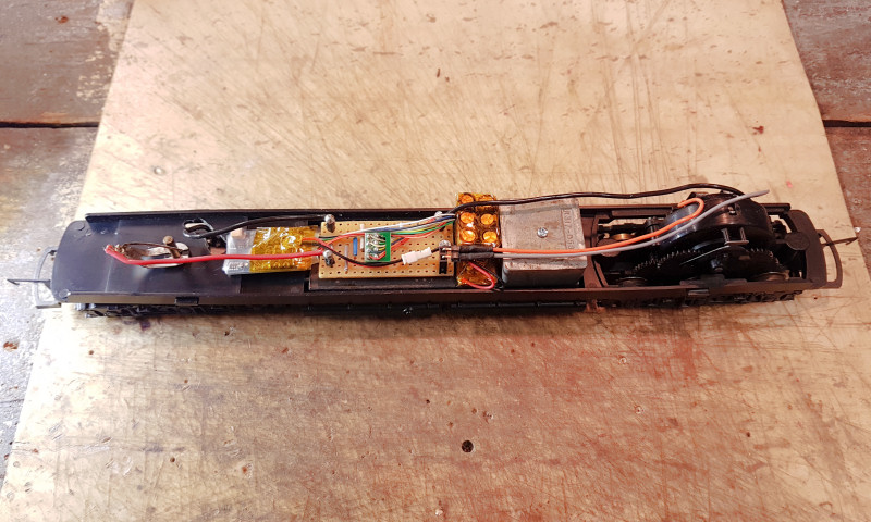
36-553 decoder and Stay Alive installed in a Lima Class 55 Deltic.
The video shows the Stay Alive powering the decoder and running motor for about 18 seconds after the track power is removed.