This page describes the control system used on the layout for many years, until it was gradually replaced by the MERG CBUS system from 2011. It is included here for completeness and because it was similar, but with subtle differences, to typical control systems used on many other layouts.
Regional Power Control
The old control system, like now, worked on the principle of regional control directed from control panels, but with the addition of switches on the panels to control the delivery of power to the track.
Each region was divided into track sections such as a platform, siding or section of mainline, and it was the control panel which governed the distribution of power to these sections, and the operation of points. Track sections, electrically isolated from their neighbours, were each powered via a single switch so that it was not possible to connect a section to more than one power source. Setting a route required the operator to press the correct buttons to set the relevant points and set the switches so that controller power was only delivered to the required track sections. An error here could result in a locomotive running onto a dead section of track or for a second locomotive to accidentally move.
Considerable operational flexibility was gained by allowing every control panel to export and import power between adjacent panels, effectively passing command of specific track sections over to neighbouring panels. This enabled a train to travel continuously from one end of the railway, through the five regions, to the other end under the direction of just one controller for the entire journey. Where appropriate, track sections were controlled by switches with three positions:
| Up | Centre | Down |
 |  |  |
| External Control | Off | Local Control |
Some track sections had multiple sources of imported power because of multiple routes between stations, and further switches (either rotary or standard) were used to select the required source. Furthermore, distinction was made between 'up' and 'down' lines so that two trains may pass each other in one region, each controlled by a second and third region. This method provided a very flexible and efficient means of control.
For more information about the control panels used on the railway, Click Here.
Locomotive Control
Each region had a dedicated power controller located at its panel. Of the five locomotive controllers, one was a single supply Gaugemaster unit (providing power to the Michel Delving region), two were home-made versions (Grey Havens and Buckland regions) and two were feedback controllers from Trax Controls (Hobbiton and Bree regions). All, except the Gaugemaster, were hand-held units linked to the control panels via a cable enabling the operator to walk around the layout as far as the wire will allow. The cables varied in length of between 1.5 and 3 metres.
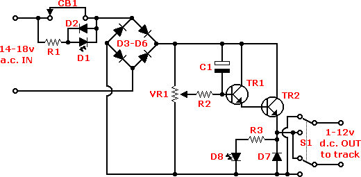
The circuit diagram below is of the railway's hand-held controllers.
All the parts should be available via either RS Components or Maplin.

| Component | Description | RS Cat. No. | Maplin Cat. No. |
| R1-R3 | 10kW resistor | 131-839 | M10K |
| VR1 | 10kW linear potentiometer | 855-462 | JM85G |
| D1 | LED (Red) - any size | ||
| D2 | 1N4148 diode | 271-606 | QL80B |
| D3-D7 | 1N4002 diode | 261-154 | QL74R |
| D8 | LED (Green) - any size | ||
| C1 | 10mF / 25V capacitor | 267-5139 | AT02C |
| TR1 | BC337 transistor | 131-1430 | QB68Y |
| TR2 | MJE3055 transistor | 313-6916 | |
| CB1 | 1 amp circuit breaker | ||
| S1 | Switch (DPDT) - ON-OFF-ON | 330-991 (toggle) | FH05F |
| Heatsink (for TR2) | 234-2328 | KU50E | |
NOTE: a heatsink must be connected to TR2 to prevent it overheating.
